Categories
Solar & Power

Solar Power Upgrade Part 3 – Self Install Running Wire

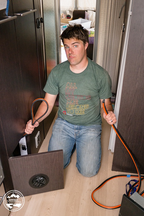
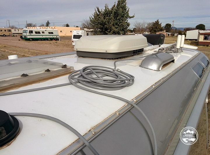
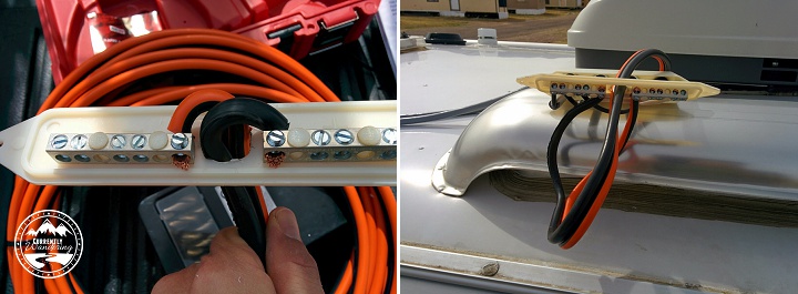
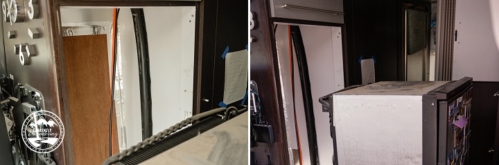
At the conclusion of Part 2, we had panels mounted on the roof and wired up to the combiner box. We connected the 6 gauge wire to the combiner box and dropped it behind the fridge. The next phase of this project involved running the wire from behind the fridge to the forward compartment. In the forward compartment, I’ll wire it up to the solar charge controller. But first, we must get there.

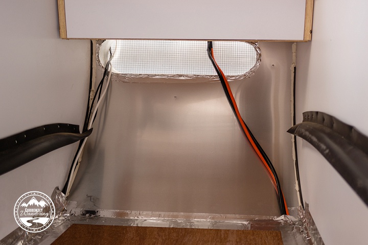
I drilled a hole in the lower segment of fridge compartment side wall. The side wall there is plywood with a metal covering. I drilled through both the metal and the wood, enlarging the holes so it fit the 6 gauge wire. That hole places the wire in the utility space underneath the wardrobe. Solar project_19
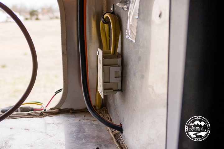
In the utility space there is one side of a wire chase that runs side to side under the hallway down the middle of the Airstream. The other end of the wire chase comes up behind the electrical panel and underneath the pantry. I pulled the electrical panel out, which is pretty easy to do. I had done it several times before, most recently to upgrade the single stage converter to a multi-stage converter. Threading the wire through that wire chase was actually easier than I had imagined. After pushing the wire into one side, I was able to pull it out of the far end using my fingers. After I had a handle on both sides, I was able to thread the remaining wire pretty quickly.

Me, looking both tired and surprised at how easy the wire chase was.

I paused my wire-running activities here to install the remote control panel for my Blue Sky solar charge controller. I measured and taped, and then drilled holes and used a small hand saw to cut the right hole for the controller in the upper kitchen cabinet. Solar project_20
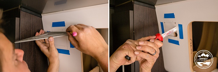
We fed the wires through a new hole in the pantry panel, and down the back of the pantry to meet up with the 6 gauge wire from the roof. There were two wires connected to the remote control: the remote control wire for the charge controller, and the shunt wire that connects to the battery monitoring shunt that I would install. After joining the main 6 gauge solar wire, these wires followed the same route for the remainder of the trip.

I then ran the wire through the side wall and above the hot water heater under the bathroom sink, later securing them with zip ties to to the underside of the shelves. I then ran the wire behind the back of the bathroom cabinets, and through a hole I drilled in the bathroom wall and into the bedroom.

My wiring route at this point is very specific to my bedroom configuration. During the remodel last year, I removed the walk-around queen and installed two rv-twin sized beds along the side walls, and a toddler sized bed in the very end. This configuration means that the remainder of my wire run is hidden underneath one of the side beds.Solar project_24

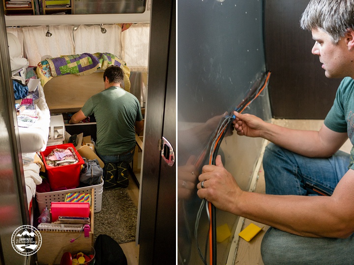
If you have a walk around queen, the wire run would not be hidden. In this case, the best solution I have seen is to run the wires along the floor, have a metal wire cover made, and screw it down to cover the wires. This solution is very nice looking, and barely noticeable at all.

I should mention here that an alternative wire run is possible. I’ve seen several installations where they ran the wire out through the bottom of the Airstream, through some conduit, and back up into the forward compartment. I didn’t like this solution for several reasons, including durability and aesthetics, but it might be a viable option if none of the other wire route paths work.

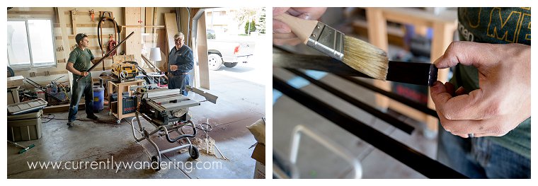
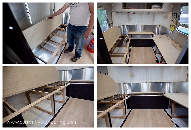
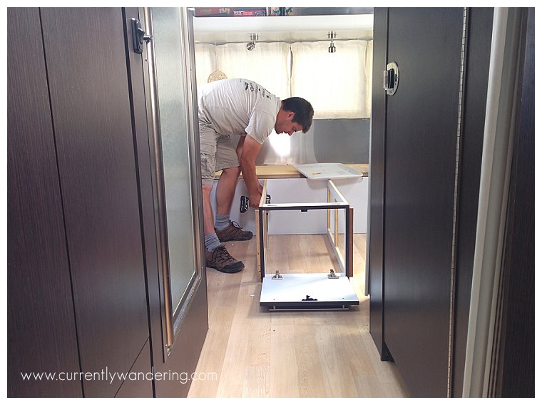
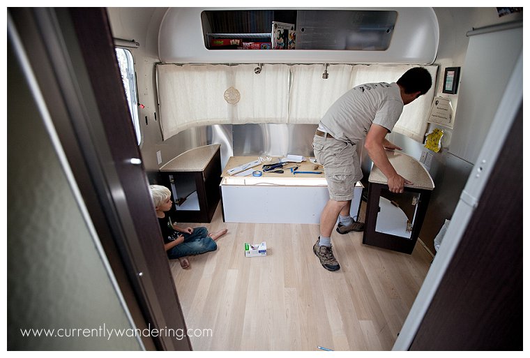
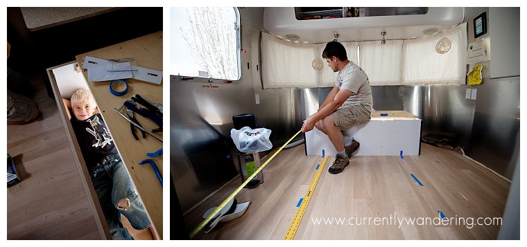
To run the wire underneath the bed, I needed to cut a notch in the vertical supports of the bed. When my Father and I designed the beds, we designed them to be removable without full disassembly. I emptied the storage compartments, removed some trim, and pulled the bed outside to make the cuts.Solar project_26

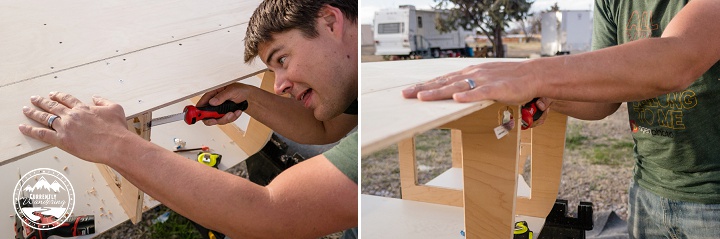
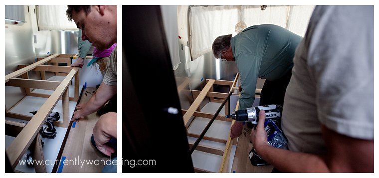
In the corner underneath the kids’ bookcases between the side bed and the back bed is a bundle of wire. During the bed remodel, I had made a cover for that wire bundle, and the added 6 gauge wire fit in just fine. I ran the wire along the same path, which led it right into the wiring panel underneath the front bed compartment.

I put the side bed back into place, replaced the electrical panel, and sealed the wire path in the fridge compartment with some silicon.

The next step is the big electrical re-wire!

Categories
Solar & Power

Solar Power Upgrade Part 2: Self-Install Combiner Box

image2
At this point of the install, each panel was mounted on the roof, with a wire connected to each panel and routed along the roof to the fridge vent. The next phase of the project requires connecting the three panels together in what is called a combiner box. Each of the negative wires are connected to a negative bus bar, and the positives to the positive bus bar. This effectively wires the panels together in parallel, which is a better setup if one of your panels ends up partially in shadow.

Two combiner boxes are possible here. If you plan to drill a hole through the roof to run the wire, a roof-top combiner box is what you need. This is the method you want to use if you plan to use the pre-installed wire many Airstreams come with for solar. I’ll explain later why this is probably a bad idea.

The second type of combiner box is called a fridge combiner box, and is used when you will be running the wire down the fridge vent instead of drilling a hole directly in the roof. Because of the type of refrigerator used in most RVs uses a heating element often powered by propane, there is usually ventilation placed above the fridge. This offers a convenient way to get cables inside without drilling holes, and is indeed the method I used to get three antenna cables inside. The fridge combiner box mounts with VHB tape and screws to the side of the fridge vent, and a hole is drilled to run the wire down the space behind the fridge and to wherever you need to route it.

The instructions provided by AMSolar are really quite good, but they really fell over during this phase of the install. The instructions want you to first mount the combiner box to the fridge vent, and then attach all the wires. This became an obviously bad idea when out of curiosity I tried to stick the 6 gauge wire pair through the indented hole in the combiner box. The wire was not even close to fitting through the hole. (See the image on the left.)

image16

At this point, I used my ‘phone a friend’ option and gave Dave Zimmerman a ring. He confirmed that the hole was ludicrously small and that heavy modification was required. I enlarged the hole with a drill, a utility knife, and most effectively a round file purchased from the hardware store in yet another run. I even went so far as to strip the end of the 6 gauge wires and test mount them to the combiner bars. This helpfully revealed that the hole needed to be even bigger to successfully bend the wires into a space small enough to fit inside the combiner box cover.

Using the combiner box as a guide, I used a sharpie to mark the size of the now-much-larger hole onto the vertical side of the fridge vent. Please excuse the poorly aimed and fuzzy picture. I took that with my spare hand with no reference to aim for a better picture. I could have mounted this box on the street side of the fridge vent, but it would be highly visible and fairly ugly. I mounted it to the opposite side, where it would be nearly entirely hidden from view. This required doing the hole-drilling work while standing high on the 8 foot ladder, leaning heavily on the fortunately sturdy fridge vent cover.

image15

Starting with the drill and finishing with the round, flat, and triangular files I bought in a set, I produced a hole large enough for the wire and dull enough not to immediately slice through the wire’s insulation. Before I removed the refrigerator for the next step, I took the time to wire each panel to the bus bars inside the combiner box. Each panel kit came with a black thing that mounted to the combiner box cover with a hole for the cable. Upon tightening this black thing with a wrench, an internal rubber gasket produced a water-tight seal against the wire to protect it from the elements. Assembling the black things to the combiner box, I pulled the panel wires through the holes and estimated their final length.

Before I proceeded, I wanted to make DARN SURE I was wiring up the panels correctly. I pulled out my little multi-meter and tested the wire from each panel. The test is easy: place the positive probe (red in my case) to the wire that should be positive, and the negative probe (black in my case) on the wire that should be negative. If the voltage reading is positive, you are correct! If the voltage reading is negative, the wires are switched. (Go ahead and switch the probes to see the negative values… it won’t hurt anything). The AMSolar Instructions had me use the black wire for positive and the white for negative, and each panel was wired correctly.

image17

I was a little surprised to see the voltage I did on each panel. Remember that in the first step, I taped a piece of cardboard over the front of the panel to keep generated voltage low. Even with nearly full blockage, I registered over 6 volts per panel! As it was, I was glad to have enough current to verify positive and negative before I completed the wiring to the combiner box.

The combiner box cover wasn’t very large, so the outer insulation of the panel wires needed to be cut to rest just inside the cover. The two internal wires were also insulated, and needed to be cut at odd lengths so that one of the wires could attach to the near bar, and the other to the far. The included instructions actually did a decent job explaining this part. After marking the desired length, I cut the wires to allow for the right length of internal wiring, then set about connecting them to the combiner box. I did this sitting on top of the 8 foot ladder, with the combiner box resting upon the fridge vent cover.

At this point, it was time to pull the fridge. I’ve done this a few times before, and it isn’t as hard now as it was the first time. First, turn off the propane valves on BOTH tanks. Second, I disconnected the DC wires from the back. Wrap those separately in electrical tape to avoid disconnecting power to the entire trailer. Next, pull the AC plug, disconnect the propane pipe, and push the fridge drain hose back through it’s holding strap. Remove the two hex-head large screws holding the metal rails to the floor. Inside, remove the four screws holding the fridge in place. The two screws on the bottom are easy to see and remove. The top screws are a little more hidden. Though possible to remove as is, I find that removing the top plastic piece (that contains the fridge temp display) makes them easier to get to. Keep track of all these screws.

The fridge can be removed by two people and set on the floor in the hallway. We used some of the panel packing cardboard to set the fridge on to prevent any damage to the floor.SAMSUNG CSC

With the fridge removed, I pushed the end of the 6 gauge wire pair through the hole in the fridge vent and went back outside. Back on the ladder, I pulled the wire out far enough to comfortably wire it into the combiner bars. At this point, I was VERY glad I had tested this first while on the ground. With all the wires attached in the combiner box, I removed the tape, applied the included putty around the hole, and stuck it to the side of the fridge vent. I drilled pilot holes and secured it with the included screws.Solar project_18

At this point, nearly all my work on the roof was done. Later on in the process, I used the included zip-ties and sticky pads to secure the panel wires to the roof in a few places. I also sealed around the feet with lap sealant as previously mentioned, and I also removed the cardboard after the wind removed one of them for me.

The next step of the process is running the wire from the fridge vent all the way through the house to the forward wiring compartment. Join me next time for more solar fun!

Categories
Bedroom Remodel Most Popular Posts

Airstream Remodel: Queen to Twins Part 2

In Part 1 of this post, we removed most of the queen, , and cut the bottoms and the tops of the beds to fit the space we needed. Now, to build the rest of the beds! Before we dive in, please enjoy this shot of me looking manly at the miter saw.

Queen to Twin Part II_009

We were very lucky in this project to have my Father, Paul, out to help for a few days. He modified a needed trip to Salt Lake City to squeeze in some help for us, and we are grateful! The project progressed much better, and faster, then it would have without his help.

Our first order of business was to cut the vertical supports for the beds. We used 3/4 inch prefinished maple plywood for these pieces. We cut out the main supports for both sides at the same time, batching parts of the process where it would help. Our plans involved several notches to allow for trim, support in the front corner, and the hinge of each bed.

We removed the centers of each support to save weight, and the savings added up. I weighed the removed centers, and it was roughly 50 lbs of weight that would NOT be added to the Airstream. The removed middle weighed more then the surrounding piece! I relied upon the engineering knowledge (and extensive experience) of my Father to leave the right amount of material to provide the necessary support. The straight lines of the middle pieces were plunge cut with a skilsaw, and the corners finished with a jig saw. We routed the inside edges to make storage access a little less sharp.
Queen to Twin Part II_001
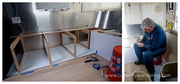
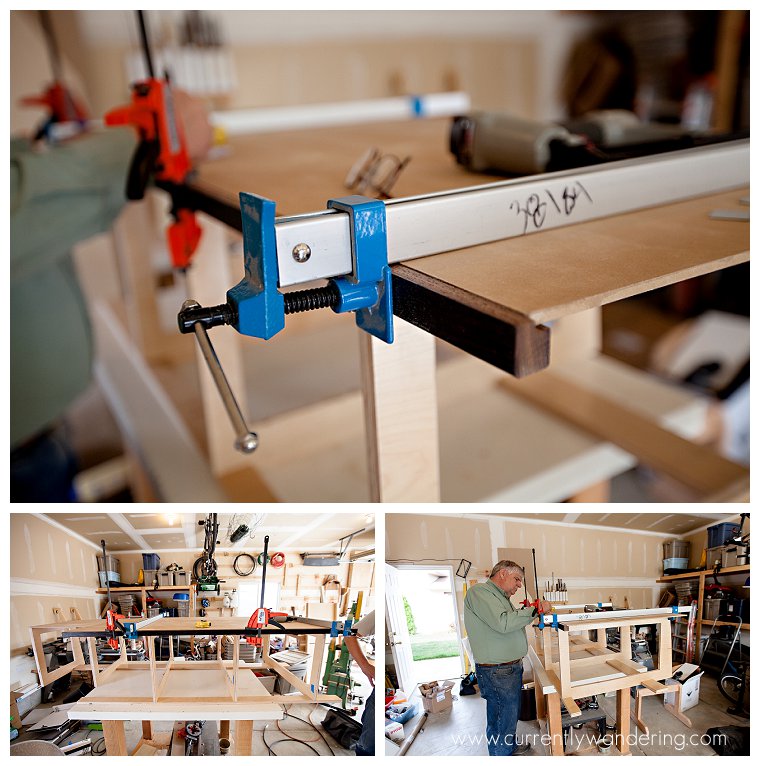
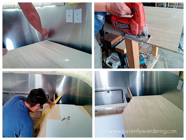
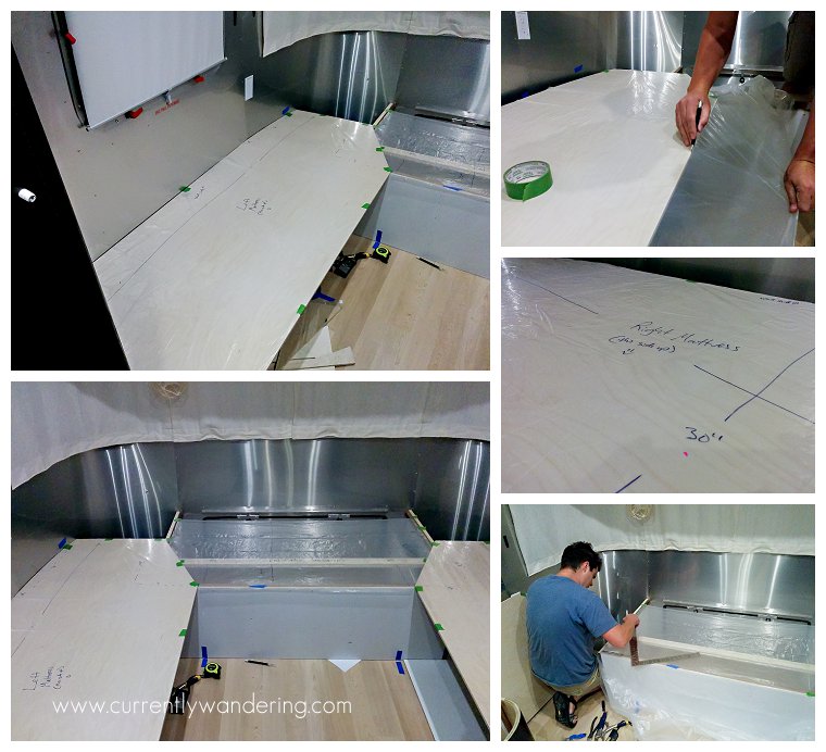
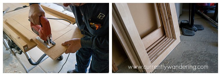
Custom work requires lots of custom fitting. We scribed and cut the back of each piece to fit the curve of the Airstream. Note the blue tape visible on the leftmost support: each piece was fit and placed in order. You can see a temporary support attached where the bed hinge will be placed, as well as the empty front notch of each support.

The beds were formed by attaching the bottom 1/4 melamine to the vertical supports with screws. This allows the entire unit to be carried in and placed in the right spot as a single unit. This picture was taken during a test fit.
Queen to Twin Part II_006

In the middle of our workday, our previously ordered mattresses arrived. Each mattress was ordered the right size and shape to fit into it’s place. The mattresses arrived with all the air removed. As we opened the packaging, the foam began to expand to it’s proper shape and thickness.

Queen to Twin Part II_010Queen to Twin Part II_011

We spent a little more than minimally necessary, and bought a three layer mattress: memory foam, air foam, and then a sturdy foam on the bottom. I’m sure they have more formal names, but that’s what we are going with for blogging purposes. They are comfortable, and we like the zippered covers they came with. The mattresses were purchased from mattressinsider.com and cost roughly $900 for all three, custom cut from our previously made templates, and shipped. As a side note, we are extremely happy with this company. They have great customer service, walked Jess through all of our options and made recommendations. They even saved our templates should we want to order custom mattress protectors or sheets!

Queen to Twin Part II_014

We decided in the middle of the first day that some trim would finish out the job nicely. I had planned on using some gel stain on some oak or poplar to match the wenge interior (dark wood) on our International CCD Airstream, but hadn’t done the purchasing yet. We took a break and drove up to MacBeath Hardwood in Salt Lake City an bought a 5 foot piece of 4/4 wenge to use as trim. At over $22 a board foot, wenge is not cheap, but you’ll see later that it was worth it.

Working that wenge was a joy. We cut off just the segments we needed (note the DARK sawdust on the garage floor) and planed it down to the desired size. One coat of finish was all it needed, and we let it dry overnight.

Queen to Twin Part II_003

The next morning, we began the final assembly of the first bed, including cutting and installing the lower trim piece you see in the picture. This piece hides the front edge of the 1/4 melamine bottom, and sticks up enough to prevent the storage bins from sliding out from under the bed while towing.

Queen to Twin Part II_008

The bottom trim was secured with finish nails and brads, both through the bottom and into the 3/4 vertical supports. You can also see here that we had finished the mdf bottom of the 1/4 melamine as a moisture prevention step. Time will tell if that was enough.

Queen to Twin Part II_018

After the first bed was in place, we made quick work of the second bed for the other side. We cut and mounted the hinges to the 3/8 baltic birch plywood bed top, and secured them in place. The back of the bed top was secured to the vertical supports to hold those corners in place, and the front corner was supported with a strip of 3/4 maple. In addition to the bottom trim, each 3/4 vertical support received a piece of wenge trim to hide the front edge of the plywood.

The last major piece shown here is the covering of the white panel you see in the first picture, just behind the orange bucket. That melamine plywood was part of the original queen, but that piece was under the middle of the bed, and not visible. It was glaring white and ugly. When we removed the queen, we removed the end tables as well. Each end table had a section of wenge veneer plywood that we reused to cover the end. We cut the usable sections of the plywood, then used biscuit joints (unglued) to align the edges together. We screwed those panels in from the inside of the storage compartment. The seam between the two panels is nearly undetectable, and the finished effect is perfect.

Queen to Twin Part II_022

Between the wenge trim on the beds, the wenge panels at the end, and the relocated heater vent (not shown), it is very difficult to tell where the original work ends and the rework begins.

You’ll notice that the beds in the pictures do not yet have gas springs as a lift assist…. because I have not yet installed them!

Continue reading Part III!

Categories
Bedroom Remodel Inside the Airstream Most Popular Posts

Airstream Bedroom Remodel: Queen to Twins, Part 1

Within  a day or so of returning home, we started our largest Airstream Project Ever. We are pulling out the queen bed, and replacing it with two twin beds and a toddler bed, leaving the walking space down the middle.

We got the party started by removing the queen bed. The bed itself is screwed into the floor in a few places, and then just screwed together. It all came out pretty easily after you find the screws.

IMG_20140412_115319_1

We left the back part of the queen bed in place as a foundation for the toddler bed at the end. We also removed the end tables, as we have plans to better use that space. With the bulk of the bed removed, it felt oddly spacious back there.

Airstream Remodel_001

With the space cleared, it was time to start planning. Also, Andrew was able to fit through the tiny gap between the hinge and remaining support.

Airstream Remodel_002

We needed to order mattresses as soon as possible, so I used the removed pieces of the bed as a spacer to prop up the plywood, then cut and fit the new bed top to fit the curves of the Airstream. We are using 3/8 baltic birch plywood for the tops of the bed. At the front (hitch end) of the trailer, the twin beds will meet the toddler bed at the corners. The mattresses will be cut at an angle to fit together.

Airstream Remodel_004

We researched mattress companies and options, and found one that would give us good quality multi-layer mattresses. After describing the shape we needed, they recommended that we cut a layer of plastic to the shape and size we needed. We cut and marked the mattress sizes, and sent them off in the mail.

Airstream Remodel_011

The remainder of the work will be done over the next few days, as we build in the rest of the beds and storage space underneath. Stay tuned!

Continue reading Part II!