Categories
Solar & Power The Airstream

Power Upgrade – 2000 Watt Pure-sine Inverter

In case anybody needs proof that I love my wife, I’ll tell you about the Inverter we installed in the Airstream. You see, my wife loves her Blendtec Blender, which checks in at 1800 watts of pure blending bliss. She found a lower-wattage hair dryer for use in the Airstream, but that Blender was going to come along with us. Prior to this upgrade, every boondock blend required hooking up the Honda 2000 generator. Since my prime motivation for this entire power upgrad was laziness, I wanted to make sure that blending was easy.

Two types of inverters exist in this world: Pure-sine wave and Modified-sine wave. The Pure-sine wave inverters produce an AC power signal that looks very much like we are used to in home wiring. Modified-sine wave generators produce an AC power signal that is ‘blocky’ and follows the desired signal with some approximation. Some electronics do just fine with a modified-sine inverter, and they are MUCH cheaper. Many advanced electronics don’t do well with the blocky signal approximation and so require the more expensive variety. I decided to buy quality in this case, and chose a pure-sine inverter.

All pure-sine inverters are expensive, but some are much more so than others. The inverter I chose was the Samlex Solar PST-2000-12 PST, which I actually purchased at BestInverter.com due to a slightly overall cheaper price. I also purchased the RC-200 Remote Control Panel for mounting out in the kitchen.

The product listing pictures of this inverter make it look quite small. Really, it is pretty darn huge. I had used measurements before purchasing to verify that I would be able to fit this where I wanted, and it fit rather well. I mounted the inverter under Cara’s bed, with the DC power connections on the side closest to the DC wiring panel. With the high amperage draws required to produce 1800 watts of AC power, the voltage drops over distance. We minimized that voltage drop by using large wire (AWS 2/0), and by keeping the run as short as possible. The design of this inverter means that the AC power cable actually comes out of the other end, but the length of the AC wire is much less of a problem than the length of the DC wire.

IMG_20150524_194142

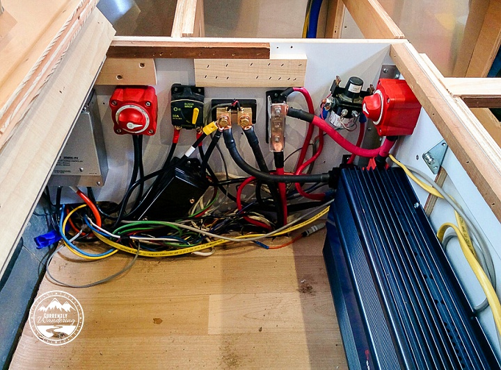
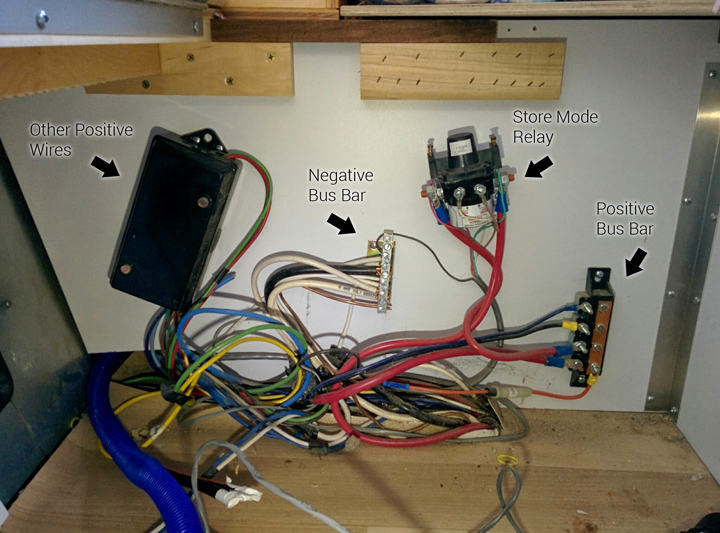
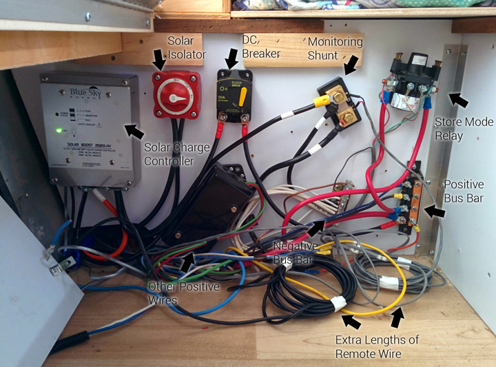
Here, for some scale, is my completed DC wire panel with most of the blue inverter visible.  (Look down below for a picture with some protective panels in place.)

When I added the inverter, I also added two additional components to my DC wiring setup. I added a 250 AMP fuse to prevent the inverter (or anything else, really) from drawing too much power through the wires. I also added a disconnect switch that could isolate the inverter from the rest of our Airstream’s DC wiring. Both of these components were wired into the positive wire leading to the Inverter.

I mentioned this on my last post about the battery upgrade, but it is worth mentioning again. The 2/0 wire that I used is very large, very stiff wire. It is nearly impossible to bend short sections of the wire to fit between the necessary mounting screws after the lugs have been crimped on. Before I crimped the ends, I made sure the wire was the needed length and bent if necessary to align as nicely as possible. I then marked the cable with a sharpie to help me align the lugs at the proper angle to make the connection. Short sections of this wire DO NOT TWIST. By being careful and triple checking my alignment and configuration, I was able to make every wire segment work properly without stressing the wire. As with nearly everything in RV life, you will have more success if you are not in a hurry.

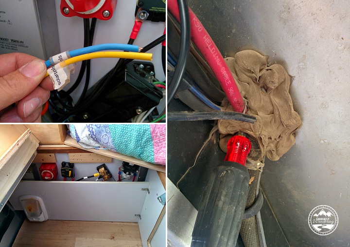
After adding the DC wire connections, I ran the remote control panel wire from the end of the inverter down to the kitchen, where I cut an appropriately sized hole underneath the Solar Charge Controller remote panel. The length of my run was just slightly longer than the remote control wired provided by Samlex, so I added a length of wire here. It is worth knowing that the cable provided is a cross-over RJ50 10p10C cable (not a straight cable). You will need to either replace the entire length of the wire with a cross-over cable, or use a 10p10C adapter to join it to the needed length of straight cable. If you don’t understand this, ask me or call Samlex and explain your situation. 10p10C cables and adapters are not very common, so you will likely need to order this online.

Cutting a new hole for the Inverter remote control below the already installed Solar Charge Controller.

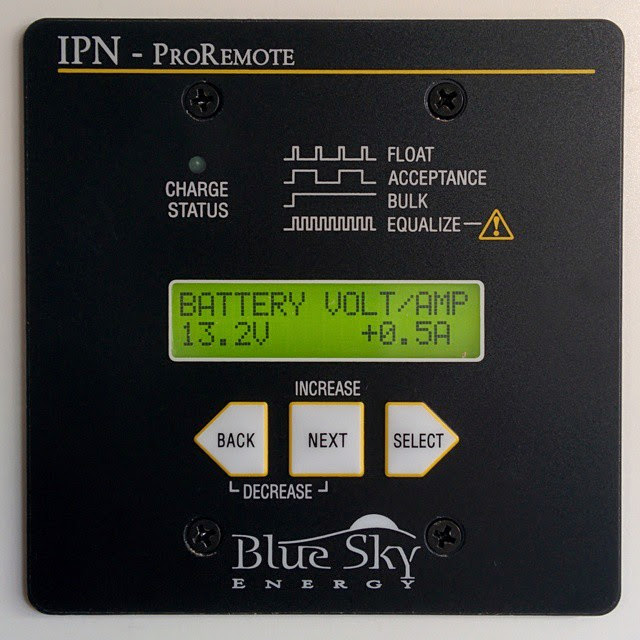
Having a remote control for the Inverter was a must for us. The inverter itself has a switch on it, but the inverter is mounted right under a sleeping kid. I did NOT want to disturb anybody just to turn the inverter on. The inverter itself does beep when turned on, but the noise isn’t super loud and it never wakes my kids up. Mounting the remote panels for the inverter and the solar charge controller also makes load monitoring easier. The solar charge controller is connected to a shunt battery monitor, which allows me to compare AC load with DC load and battery voltage. I highly recommend getting remote panels and mounting them someplace convenient.

The last wire to add was the AC wire running from the inverter to my AC panel in the kitchen. (I actually ran this at the same time as the control wire above.) This was a simple task, though the process of wiring it into the Airstream’s AC system was complicated enough that I’m going to write about that in a dedicated post.

Installing the DC wiring was tough, but a good thing to get finished in my project. The wires themselves are hidden behind a panel that I modified to fit the inverter. I also added some wood that covers the top of the main DC fuse to prevent things from dropping on it.

IMG_20150525_154223

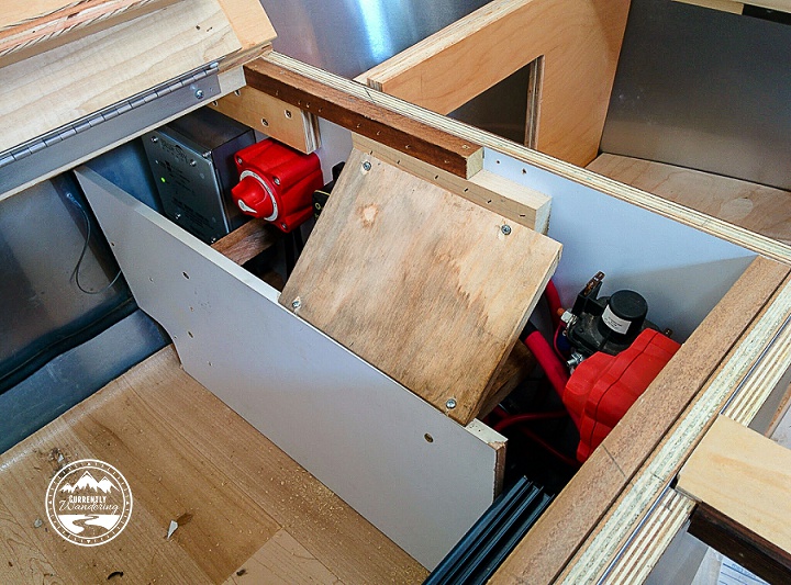
And here we are, with the DC power stuff complete and only the AC wiring left to complete.

Categories
Solar & Power

Solar Power Upgrade Part 4 – The Wire Panel

With the solar mounted on top (part 1, part 2) and the wires run to the forward compartment (part 3), there was only one thing left to do. The next step in my project was to connect it all up!

Underneath Cara’s bed is the wiring panel where the battery is connected to the rest of the DC wiring. This is a prime location for the solar charge controller because of it’s proximity to the batteries. Later, I’ll install the inverter nearby for the same proximal reason. The existing wiring in this location was a positive bus bar, a negative bus bar, the ‘store’ mode disconnect relay, and a positive DC breakout box.

IMG_20150223_075750_labels

Also found in this location was the ends of the solar pre-wire placed by Airstream. I knew they were there, but the wire gauge was so small that I had to replace it anyway.

As I was adding plenty of components, I had to do a little rearranging of the existing components. They were just screwed into the plywood panel, and I was able to re-arrange them without too much difficulty.

IMG_20150223_144008_labels

In principle, the solar panels are wired to the solar charge controller, and the solar charge controller is wired to the positive and negative bus bars. In practice, there are a few additional details.

The first component I installed was the isolator switch on the positive wire leading from the solar panels. By switching this off, I was able to protect myself (and the equipment) from an accidental short during the rest of my wiring project. (A ‘short’ is when you accidentally connect two wires that are not meant to be connected. Ever accidentally touch the clamps of a jump start cable together? That is a short.) After installing the isolator switch, I left it off for the rest of my install.

I next wired up the solar charge controller. A short run from the just installed isolator switch on the positive side, and the negative side of the cable from the rooftop panels. The next step involved connecting the ‘out’ side of the controller to the existing DC system. The positive side of this connection is run through a switchable 30 amp DC breaker. This switch automatically flips off if the solar charge controller attempts to output more than 30 amps. With a maximum output of approximately 24 amps, I suspect this will never trip. It DOES serve as additional protection, and also as an extra isolator switch should I manually switch it off. The positive side is then wired to the positive bus bar.

The negative side of the charge controller ‘out’ connection can be wired directly to the DC bus bar, but I cheated slightly and attached it to our last new component: The battery monitoring shunt. This magical component can measure the flow of electricity from one side to the other. This enables both a real-time view of charge/drain activity on the battery, as well as keeping track of how many ‘amps’ or amp-hours are left in your battery. This measure is unaffected by load (like voltage) and gives a great indicator of battery charge state at a glance.

The monitoring shunt is installed between the negative terminal of the battery and the rest of the negative half of the DC system. I moved the negative battery cable from the DC bus bar and connected it to one side of the shunt, and added a new cable between the other side and the DC bus bar. Now, every use of DC power can be monitored. More on that later.

I connected the negative side of the charge controller DC ‘out’ to the shunt as well, on the non-battery side. (ONLY the battery should be connected on that side of the shunt. EVERYTHING else is connected on the other side.)

At this point, everything ‘major’ is in place. In part 3 of this series, I mentioned running remote cables from the kitchen cabinet down to the electrical panel and along the same run as the solar wire. At this point, I attached these remote wires to their various components. The IPN Pro Remote cable attached to the solar charge controller. The shunt monitoring cable attached to the shunt with little screw mounts.

The last step I’ll describe was really the hardest step of this last phase. The solar charge controller has a remote temperature sensor that allows it to adjust it’s charging based on the temperature of the battery. This cable attaches to a battery terminal in the battery box, and to the solar charge controller inside the Airstream. The existing battery cables are run through a heavily caulked hole in the floor. By poking carefully with a phillips screwdriver, I was able to poke a hole through the middle of the bundle without damaging any existing wire. After attaching it to the battery and threading it out of the battery box, I ran it alongside the battery wires, and protected it with some plastic wire wrap. I shoved it through the hole I poked, and then squooze a bunch of silicon sealant around the wire from the top and the bottom. The sensor attached easily to the charge controller, and then I attached the cover.

IMG_20150223_132519
The weak-sauce wires prewired for solar, my screwdriver hole making method for the temperature sensor, and how it all looked with the protective panel reinstalled.

At this point, everything was installed. I only needed a short length of wire and a few wire terminals from the store, and everything else was provided in the installation kit from AM Solar. Between their instructions and the inspection of Dave Zimmerman’s wiring, I was able to work out all the details and complete the self install.

The only thing left to do was to flip the system on. I started with the solar isolator switch, but nothing lit up upon flipping that on. Next was the 30 Amp breaker, and that did the trick. Things started blinking, the power in the Airstream worked again, and I immediately started my addictive ‘check the solar monitor’ habit.

10919134_454446811386230_1784970774_n

Really, I’m surprised that everything worked out as well as it did. I re-attached the plywood panel that covers the wiring, and the project was complete. Really, I had a few random things to do, like zip-tie wires in various places, but it all feels better when the darn thing works!