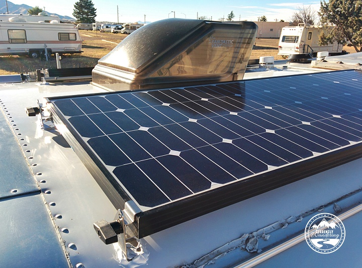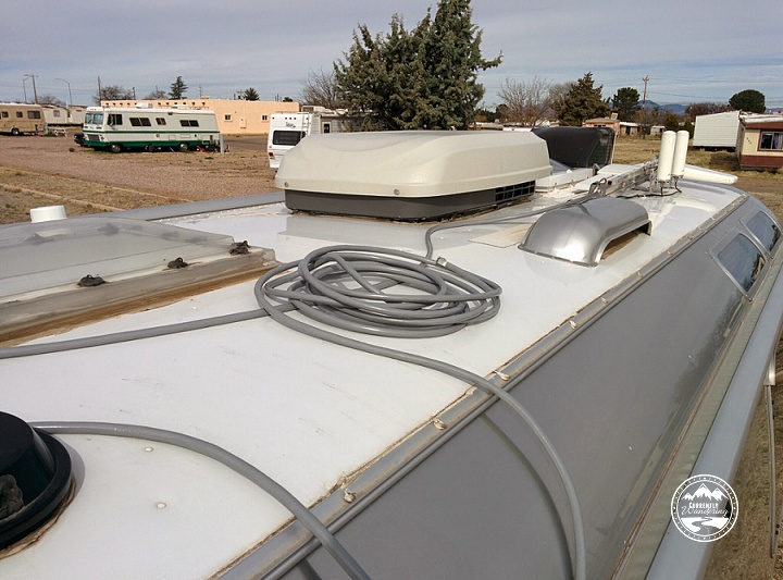
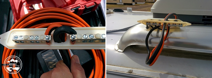
At this point of the install, each panel was mounted on the roof, with a wire connected to each panel and routed along the roof to the fridge vent. The next phase of the project requires connecting the three panels together in what is called a combiner box. Each of the negative wires are connected to a negative bus bar, and the positives to the positive bus bar. This effectively wires the panels together in parallel, which is a better setup if one of your panels ends up partially in shadow.
Two combiner boxes are possible here. If you plan to drill a hole through the roof to run the wire, a roof-top combiner box is what you need. This is the method you want to use if you plan to use the pre-installed wire many Airstreams come with for solar. I’ll explain later why this is probably a bad idea.
The second type of combiner box is called a fridge combiner box, and is used when you will be running the wire down the fridge vent instead of drilling a hole directly in the roof. Because of the type of refrigerator used in most RVs uses a heating element often powered by propane, there is usually ventilation placed above the fridge. This offers a convenient way to get cables inside without drilling holes, and is indeed the method I used to get three antenna cables inside. The fridge combiner box mounts with VHB tape and screws to the side of the fridge vent, and a hole is drilled to run the wire down the space behind the fridge and to wherever you need to route it.
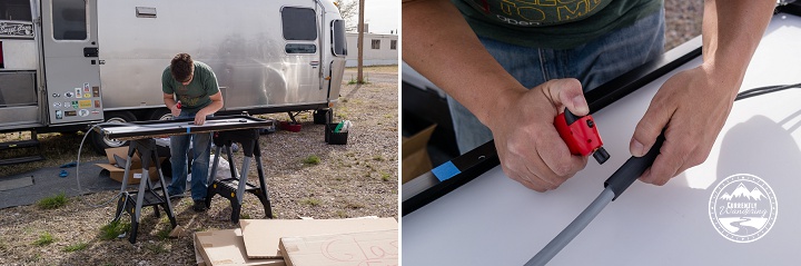
The instructions provided by AMSolar are really quite good, but they really fell over during this phase of the install. The instructions want you to first mount the combiner box to the fridge vent, and then attach all the wires. This became an obviously bad idea when out of curiosity I tried to stick the 6 gauge wire pair through the indented hole in the combiner box. The wire was not even close to fitting through the hole. (See the image on the left.)
At this point, I used my ‘phone a friend’ option and gave Dave Zimmerman a ring. He confirmed that the hole was ludicrously small and that heavy modification was required. I enlarged the hole with a drill, a utility knife, and most effectively a round file purchased from the hardware store in yet another run. I even went so far as to strip the end of the 6 gauge wires and test mount them to the combiner bars. This helpfully revealed that the hole needed to be even bigger to successfully bend the wires into a space small enough to fit inside the combiner box cover.
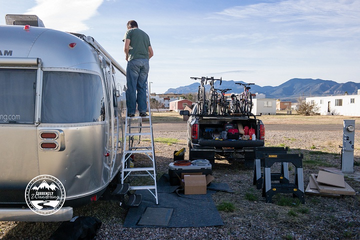
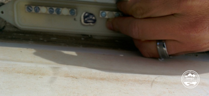
Using the combiner box as a guide, I used a sharpie to mark the size of the now-much-larger hole onto the vertical side of the fridge vent. Please excuse the poorly aimed and fuzzy picture. I took that with my spare hand with no reference to aim for a better picture. I could have mounted this box on the street side of the fridge vent, but it would be highly visible and fairly ugly. I mounted it to the opposite side, where it would be nearly entirely hidden from view. This required doing the hole-drilling work while standing high on the 8 foot ladder, leaning heavily on the fortunately sturdy fridge vent cover.
Starting with the drill and finishing with the round, flat, and triangular files I bought in a set, I produced a hole large enough for the wire and dull enough not to immediately slice through the wire’s insulation. Before I removed the refrigerator for the next step, I took the time to wire each panel to the bus bars inside the combiner box. Each panel kit came with a black thing that mounted to the combiner box cover with a hole for the cable. Upon tightening this black thing with a wrench, an internal rubber gasket produced a water-tight seal against the wire to protect it from the elements. Assembling the black things to the combiner box, I pulled the panel wires through the holes and estimated their final length.
Before I proceeded, I wanted to make DARN SURE I was wiring up the panels correctly. I pulled out my little multi-meter and tested the wire from each panel. The test is easy: place the positive probe (red in my case) to the wire that should be positive, and the negative probe (black in my case) on the wire that should be negative. If the voltage reading is positive, you are correct! If the voltage reading is negative, the wires are switched. (Go ahead and switch the probes to see the negative values… it won’t hurt anything). The AMSolar Instructions had me use the black wire for positive and the white for negative, and each panel was wired correctly.
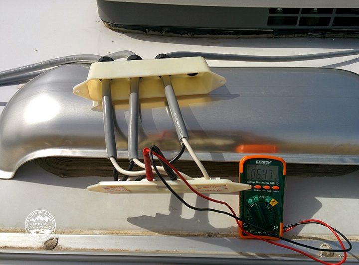
I was a little surprised to see the voltage I did on each panel. Remember that in the first step, I taped a piece of cardboard over the front of the panel to keep generated voltage low. Even with nearly full blockage, I registered over 6 volts per panel! As it was, I was glad to have enough current to verify positive and negative before I completed the wiring to the combiner box.
The combiner box cover wasn’t very large, so the outer insulation of the panel wires needed to be cut to rest just inside the cover. The two internal wires were also insulated, and needed to be cut at odd lengths so that one of the wires could attach to the near bar, and the other to the far. The included instructions actually did a decent job explaining this part. After marking the desired length, I cut the wires to allow for the right length of internal wiring, then set about connecting them to the combiner box. I did this sitting on top of the 8 foot ladder, with the combiner box resting upon the fridge vent cover.
At this point, it was time to pull the fridge. I’ve done this a few times before, and it isn’t as hard now as it was the first time. First, turn off the propane valves on BOTH tanks. Second, I disconnected the DC wires from the back. Wrap those separately in electrical tape to avoid disconnecting power to the entire trailer. Next, pull the AC plug, disconnect the propane pipe, and push the fridge drain hose back through it’s holding strap. Remove the two hex-head large screws holding the metal rails to the floor. Inside, remove the four screws holding the fridge in place. The two screws on the bottom are easy to see and remove. The top screws are a little more hidden. Though possible to remove as is, I find that removing the top plastic piece (that contains the fridge temp display) makes them easier to get to. Keep track of all these screws.
The fridge can be removed by two people and set on the floor in the hallway. We used some of the panel packing cardboard to set the fridge on to prevent any damage to the floor.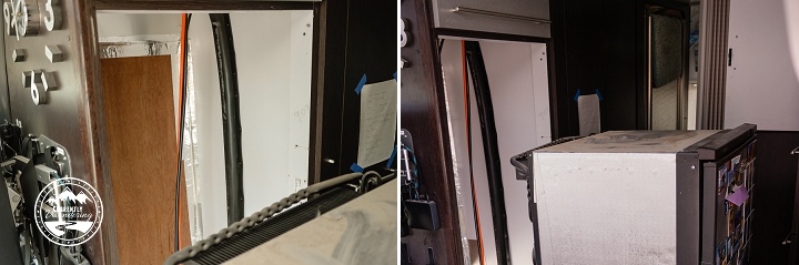
With the fridge removed, I pushed the end of the 6 gauge wire pair through the hole in the fridge vent and went back outside. Back on the ladder, I pulled the wire out far enough to comfortably wire it into the combiner bars. At this point, I was VERY glad I had tested this first while on the ground. With all the wires attached in the combiner box, I removed the tape, applied the included putty around the hole, and stuck it to the side of the fridge vent. I drilled pilot holes and secured it with the included screws.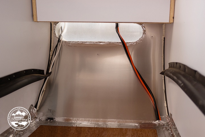
At this point, nearly all my work on the roof was done. Later on in the process, I used the included zip-ties and sticky pads to secure the panel wires to the roof in a few places. I also sealed around the feet with lap sealant as previously mentioned, and I also removed the cardboard after the wind removed one of them for me.
The next step of the process is running the wire from the fridge vent all the way through the house to the forward wiring compartment. Join me next time for more solar fun!